Quick guide
To get your Arduino to control a plotter, following steps are needed:
Windows USB driver
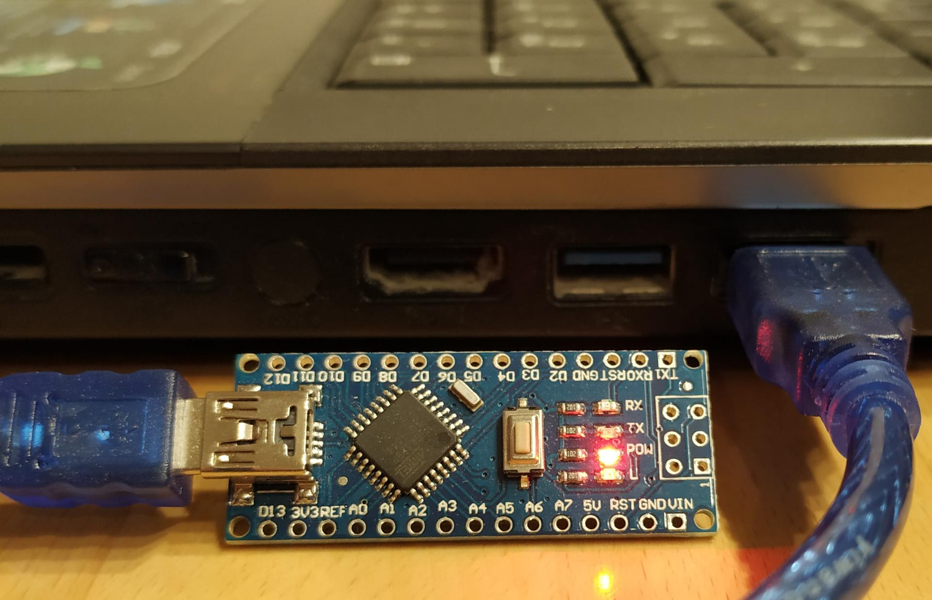 Connect your Arduino with your PC, on windows 10 the needed USB driver will be installed automatically, if not: the cheap Arduino clones often uses a CH340 chip. Check here for more information https://www.google.de/search?q=arduino+ch340.
Grbl firmware
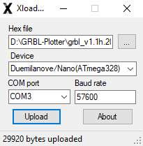 Download and start "GRBL-Plotter_Setup.exe" from GRBL-Plotter. Start the program XLoader.exe from the folder "GRBL-Plotter\Firmware\_XLoader". Select the desired firmware (Hex file), correct device and the correct com port, then upload the firmware. With the shown settings, the upload took 18 seconds.
Check my github for some updates.
- grbl_v1.1h.20190825.hex is the latest regular grbl firmware for Arduino uno and nano, from https://github.com/gnea/grbl
- grbl_v1.1f_Servo.hex as above, but with Spindle-PWM adapted to RC-Servo specification (1ms - 2ms), from https://github.com/cprezzi/grbl-servo see also 'use of servo' below
- grbl_v1.1f_Servo_switch_dir_step.hex as above, but with Spindle-PWM adapted to RC-Servo specification (1ms - 2ms) and step/dir pins swapped for use with CNC Shield V4 for Arduino nano (see below), from https://github.com/cprezzi/grbl-servo
- grbl-Mega-5X-v1.1l.20190605.hex 5 axis version for Arduino Mega2560 only, from https://github.com/fra589/grbl-Mega-5X
After successful upload, close XLoader and reset the controller.
1st connection
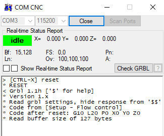 Install GRBL-Plotter by starting 'setup.exe' from the unzipped folder. Start GRBL-Plotter and select the correct COM-port for the controller. After successful connection, grbl sends a start-up message "Grbl 1.1h ['$' for help]".
Now the buttons inside the GUI are enabled and the stepper motors can be controlled.
Configuration of grbl
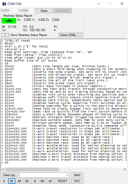 After pressing "$$", grbl lists the stepper motor settings, which must be adapted for each machine. Check the grbl-Wiki for more information. The screenshoot shows the initial settings after the installation of grbl.
The main settings are $3, $10x, $11x (x=0,1 or 2 depending on axis) to get the stepper motors running in the correct direction. The correct direction means:
- +X = to the right
- +Y = to the back
- +Z = upwards
Note: a too large number for $10x (steps/mm) and $11x (max. speed) will cause problems.
The product of $10x and $11x must stay below 1800000 to avoid pin frequencies above 30 kHz.
E.g. $100=250, $110 = 7200 is at the edge.
More information here: quick-guide-to-setting-up-your-machine-for-the-first-time

Alternative setup form opens via $$ command or 'Machine Control' menu item.
Basic configuration of GRBL-Plotter
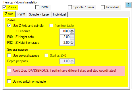 The main task of GRBL-Plotter is to convert graphics into GCode for your machine (router, plotter, laser engraver). To convert the pen up/down to your needs (Z-axis, PWM for RC-Servo, switch for Laser) set the needed pen up/down translation here [Menu - File - Setup - Graphics import - G-Code generation]: Pen up/down translation.
Now the first graphic can be converted, e.g. via drag and drop (onto the 2D view) - try:

To display the fill color, select 'Apply hatch fill if object is filled' here [Menu - File - Setup - Graphics import - Path import - General options]: Formate related options.
Example: Micro plotter from DVD drives and manual pen change
Spindle-PWM and use of a servo:
The pulse width modulation (PWM) for speed control of a motor or power control of a laser, is generated via a special pin function (hardware PWM) inside the ATmega328 (the microcontroller of the Arduino Uno / nano) on pin 11 (PB3, OC2A). This means the pin for the output of the PWM cannot be changed.
- By default, the PWM frequency is set to 1 kHz. The duty cycle can be controlled between 0% and 100% to get an control voltage of 0V to 5V for the spindle or laser.
- RC servos usually require a PWM signal of 50 Hz with a pulse width of 1 ms to 2 ms. The duty cycle is then just in the range of 5% to 10% - not suitable to control a spindle or laser.
- Workaround: With a 'converter', the needed signal can be generated from an on/off or Spindle-PWM signal, check Plotter-ServoControl
Regular grbl: "By default, the spindle PWM frequency is 1kHz, which is the recommended PWM frequency for most current Grbl-compatible lasers system. If a different frequency is required, this may be altered by editing the cpu_map.h file."
Source: https://github.com/gnea/grbl/wiki/Grbl-v1.1-Laser-Mode#laser-mode-operation
Adapted grbl: "This is a special version with servo support (swichable in config.h) The PWM frequency is set to 61Hz (prescaler 1/1024). The pulse width range is 0.5 - 2.5ms." (Duty cycle it then from 3% to 15%).
Note: internally the PWM range goes from 7 (0.5 ms pulse width) to 38 (2.5 ms pulse width), which results to 32 possible different servo positions (probably less, because the regular range is from 1 ms to 2 ms). Source: https://github.com/cprezzi/grbl-servo
Common hardware
The following information refers to cheap (counterfeit?) boards that are available on ebay for 12€ to 15€ (including shield, arduino, A4988 drivers and USB cable).
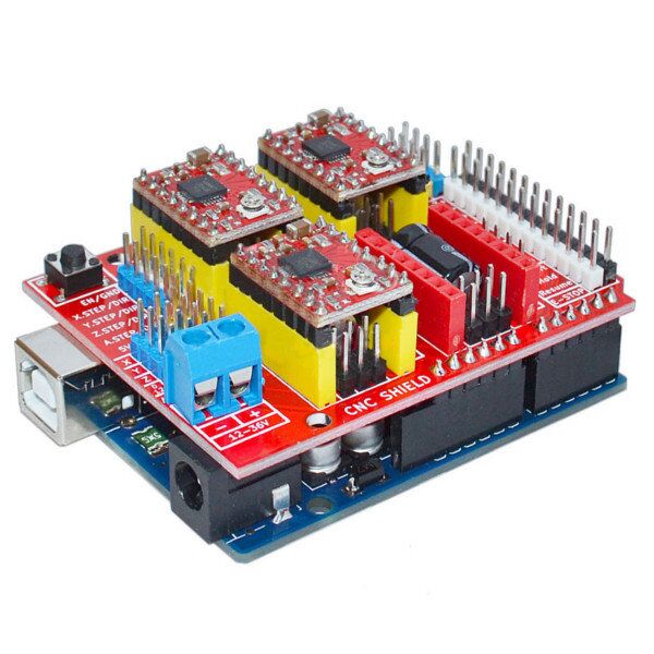 The CNC shield V3 for Arduino Uno was designed for grbl 0.9. Because of a change in the pin-out in grbl version 1.1 (pin 11 and 12 are swapped), the spindle-pwm signal can be found on the Z+ pin. Check schematic here.
Free E-Book about the shield: CNC Shield V3 development board and Maker Store CNC Shield Guide
My recommendation:
- Use the original grbl version 1.1 configuration (no pin-swap in config.h / cpu_map.h)
- Connect the spindle/laser/servo at CNC-Shield pin 'Z-Endstop', if you don't need PWM to control the speed, then just send 100% speed (usually S1000)
- Connect the Z end switch with CNC-Shield pin 'Spindle Enable'
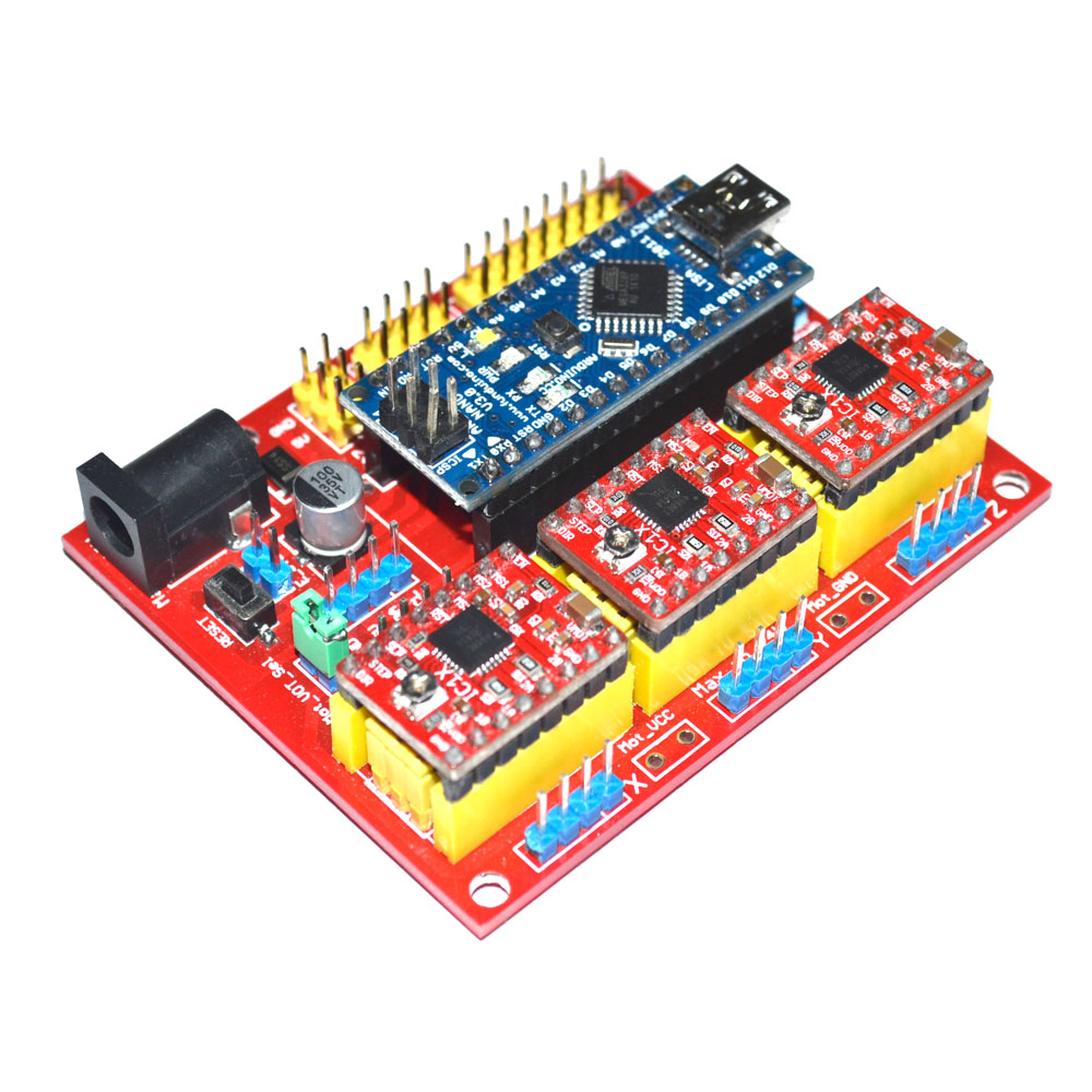 The CNC shield V4 for Arduino nano shows a wrong layout for the micro-step jumpers. Check this link. Also step and dir-signals are swapped, which needs a adapted grbl version. I used this board at my foldable plotter. The adapted grbl firmware can be found in the GRBL plotter setup (grbl_v1.1f_Servo_switch_dir_step.hex).
Using old pc
Windows XP: the regular setup (file 'GRBL-Plotter_Setup.exe') doesnt work (setup is made with Inno-Setup, which supports down to Windows Vista), instead use the extracted folder from 'GRBL-Plotter_1xxx_release.zip' and start 'GRBL-Plotter.exe'.
Signs for a slow computer: frequent occurance of grbl-errors, like
- error:20 Unsupported or invalid g-code command found in block.
- error:24 More than one g-code command that requires axis words found in block.
- error:2 Missing the expected G-code word value or numeric value format is not valid.
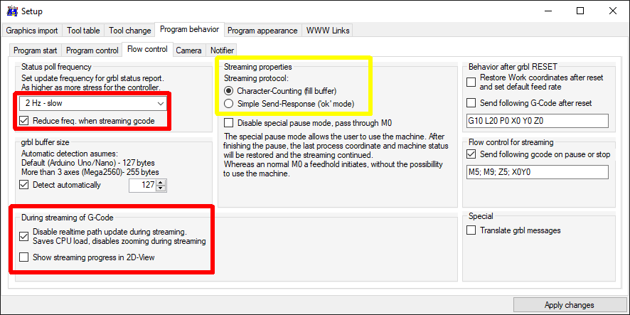
If the pc hardware is slow (like old pc with windows XP), some options should be changed to the shown settings:
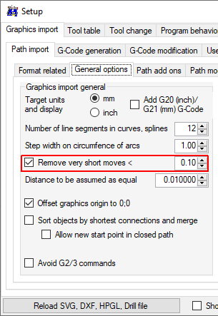
Also try to reduce data-amount during import, e.g. plotters don't need step-width of 0.001 mm:
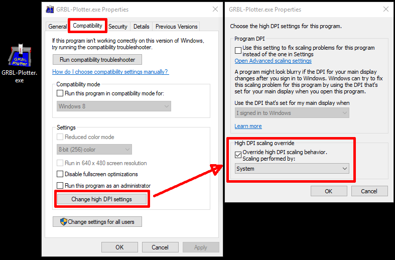
High DPI setting
If you use a high DPI monitor with higher resolution-setting than 100%, the GRBL-Plotter GUI will adapt it's size. Unfortunatly, after importing a graphic the size shrinks...
To avoid this behavior, do the setting, shown below (right click on the icon - Properties):