Convert Image
G-Code Creation: [Text] [Barcode] [Image] [Simple shapes] [Jog path] [Extensions]
Workpiece: [Probing] [Height map]
Machine: [Laser tools] [Coordinate systems] [DIY Control] [Camera] [Process automation]
back to [Menu]
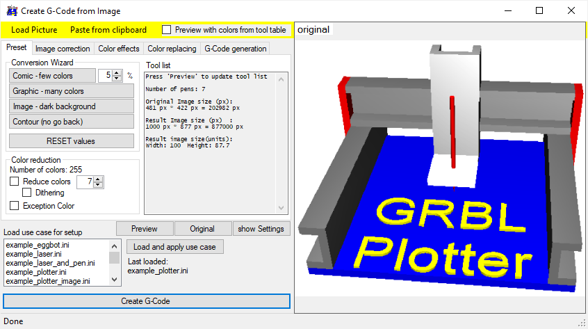
With the first tab 'Start' the general task must be selected.
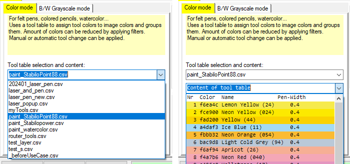
In 'Color mode' the original image colors will be replaced by the nearest colors given in the selected tool table. Select tool table and check available colors here. Also tool change options can be selected.
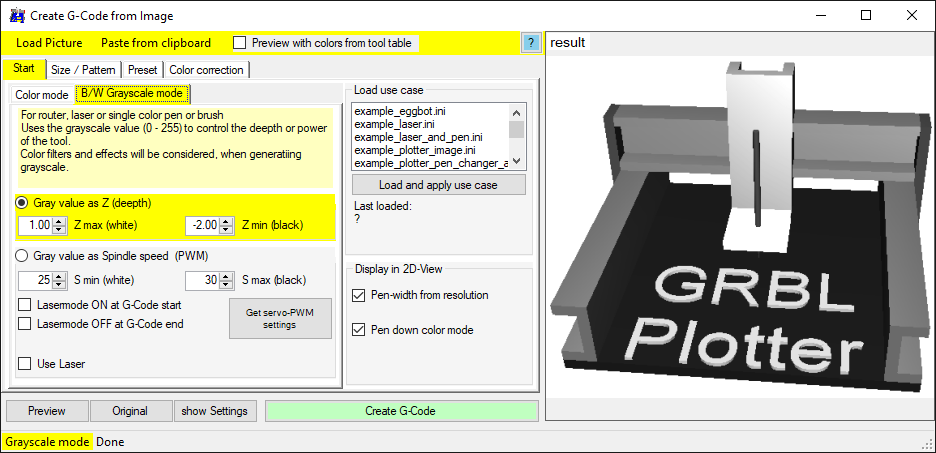
In 'B/W Grayscale mode' the original image colors will be converted to gray values. The gray values will then be interpreated as height information. The height information can be translated into Z-axis positions or PWM value to control a laser or RC-Servo.
Example: Video Halftone plotting using grbl laser mode
In the second tab 'Size / pattern', the result size and drawing behave can be defined.
Line tracing: for grayscale mode - the pixel values below an overlaying pattern will be taken. The overlaying pattern can be 'Line by line' or 'Spiral' or self defined pattern. Check video above and: Adjusting pen-width via Z axis used settings
Vectorization: for color mode - each image colors will be vectoriced seperatly. Example: Video Mini CNC Easter greetings
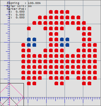
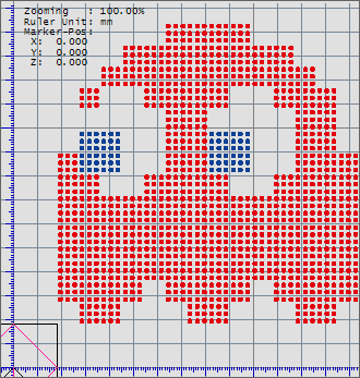
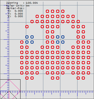
Pixel art: each image pixel will be translated to a dot. Example: Video Santa Claus pixel art
Results - using 1 dot / pixel, using 3x3 dots / pixel, using shape circle instead of a dot:

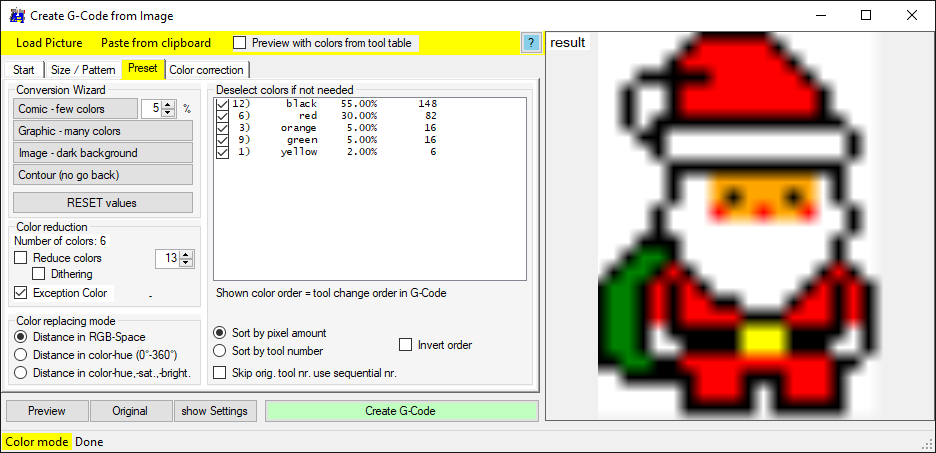
With the third tab 'Preset', the actual used tool table colors will be shown. Via the 'Conversion wizzard' you can try to minimze the number of tools with low quality lost.
The found tool colors can be deselcted and sorted, to change the order of usage in the created G-Code.
It make sense to start with a bright color and end with a dark color. Otherwise you may contaminate bright felt pens with drawing over already drawn dark areas.

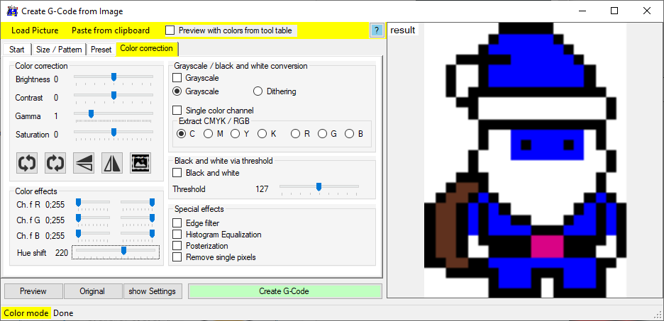
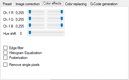
In the tab 'Color correction' the original image colors can be changed to get some effects - e.g. 'Hue shift'.
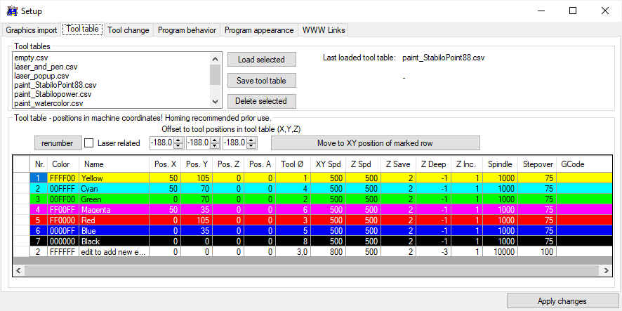
Tool table: