Camera
G-Code Creation: [Text] [Barcode] [Image] [Simple shapes] [Jog path] [Extensions]
Workpiece: [Probing] [Height map]
Machine: [Laser tools] [Coordinate systems] [DIY Control] [Camera] [Process automation]
back to [Menu]
Camera setup
- The camera can be mounted fix or movable (mounted on XY-platform or XY-moved Z axis).
- For each mounting option (fix or movable) a setup (video source, distorion, rotation, scaling) will be stored
Setup of fix mounted camera
Setup of a movable mounted camera
Fix mounted camera

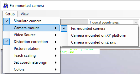
- Select type of mounting = 'Fix mounted camera'
- Disable "Simulate Camera" to get a live image
- Disable "Distorion correction", to get the full image
- Select correct Video source
Set markers for the field of view in the right ratio 4:3. This area will be zoomed to the size 640 * 480 px.
I took a din A4 paper and marked 28 cm x 21 cm. And centered the paper to the working area (which is just 20 cm x 15 cm) of my plotter.
For minimal distortion, try to place the web-cam centric above the paper.
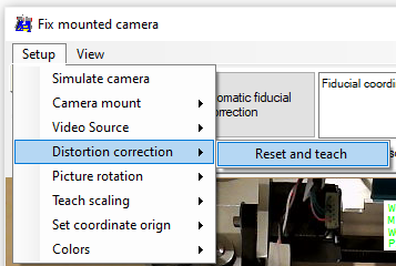
Distortion correction
To remove distortion, caused by the camera angle, apply 'Distortion correction' and teach the four corners of the markers.
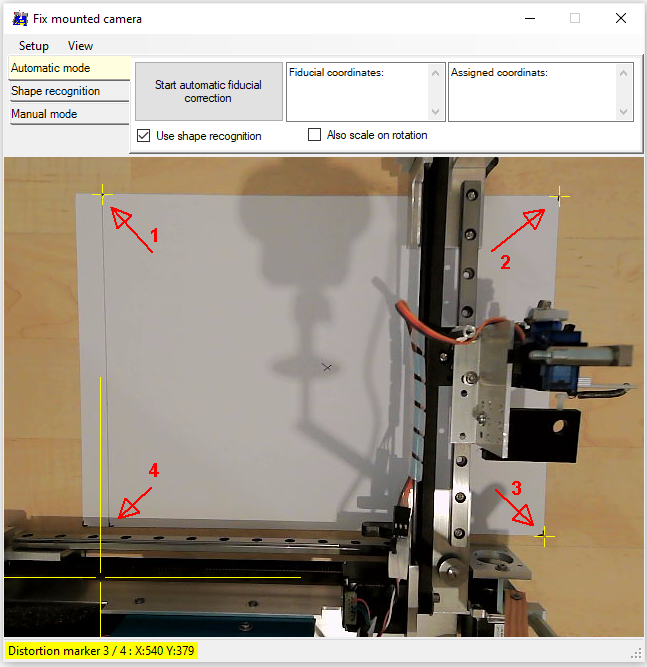
Teach the corners of the markers, start with the upper-left, then upper-right, lower-right and finally lower-left. Small yellow crosses marking the teached positions.
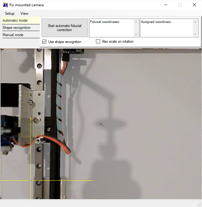
After setting the 'Picture rotation' to 180°, the view is like this.
The previously marked positions are now the edges of the image.
Load a reference pattern (ruler.dxf) to teach the offset and scaling of the image.
Move to the most lower-left position, set work-pos. to 0;0 and plot the pattern.
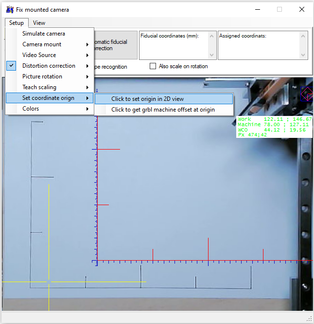
Select 'Set coordinate origin' and "Click to set origin in the 2D view" - the 0;0 coordinate of the drawn ruler on the paper.
Move to work position 0;0 and press "Click to get grbl machine offset at origin".
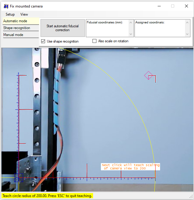
Select 'Teach scaling' to teach a distance of given amount ('Set teach radius') - I choosed 200
Movable mounted camera
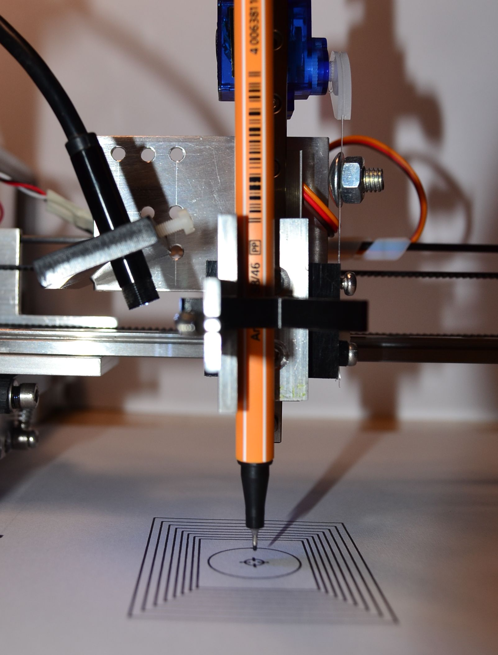
I use a "Water-proof Pipe Inspection Camera" or "Endoscope Video Cam"
Select type of mounting = 'Camera mounted on XY platform'
Select Video source
Set work position offset to 0;0
Load (without offset correction) and draw 'DistortionPattern.dxf'.
Finally move pen back to 0;0 = center of this pattern.
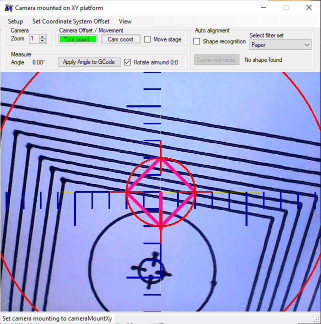
Align camera as best as possible to center the pattern.
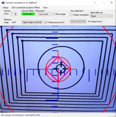
Distortion correction
To remove distortion, caused by the camera angle, apply 'Distortion correction' and teach four corners of the same rectangle.
This area will be zoomed to the size of 640 * 480 px.
Select 'Teach scaling' to teach the radius of the circle, in my pattern it is 10.